How to properly prepare a DXF file for laser cutting
Proper DXF file preparation is key to accurate and cost-effective parts. Layers, line widths and tolerances, ten illustrated mistakes, the exact specification our configurator expects, and what its pricing messages mean.
DXF (Drawing Exchange Format) is the standard format for exchanging CAD data. In laser cutting, the quality of this file is directly proportional to the quality of the finished part — and its cost.
Layer setup
Use separate layers for cutting contours, engraving, and annotation lines. The cutting layer should have a line width of 0.00 mm (hairline) — any other value may cause incorrect interpretation of the laser path.
Closed contours and duplicates
Every contour must be closed — open ends cause the laser to cut the shape incorrectly. Also check for duplicate lines in the same location: a double cut unnecessarily increases the cost and may damage the material.
Steps before submission
- Check layer settings — cutting on a separate layer
- Make sure all lines are closed contours
- Export in DXF version R12 or R14
- Verify file dimensions against actual part dimensions
- Remove helper lines, dimensions, and annotation text
Minimum dimensions
The smallest hole should have a diameter at least equal to the material thickness. For a 3 mm sheet, the minimum hole is 3 mm. Smaller holes cannot be cut cleanly by the laser.
When to attach a drawing to the DXF
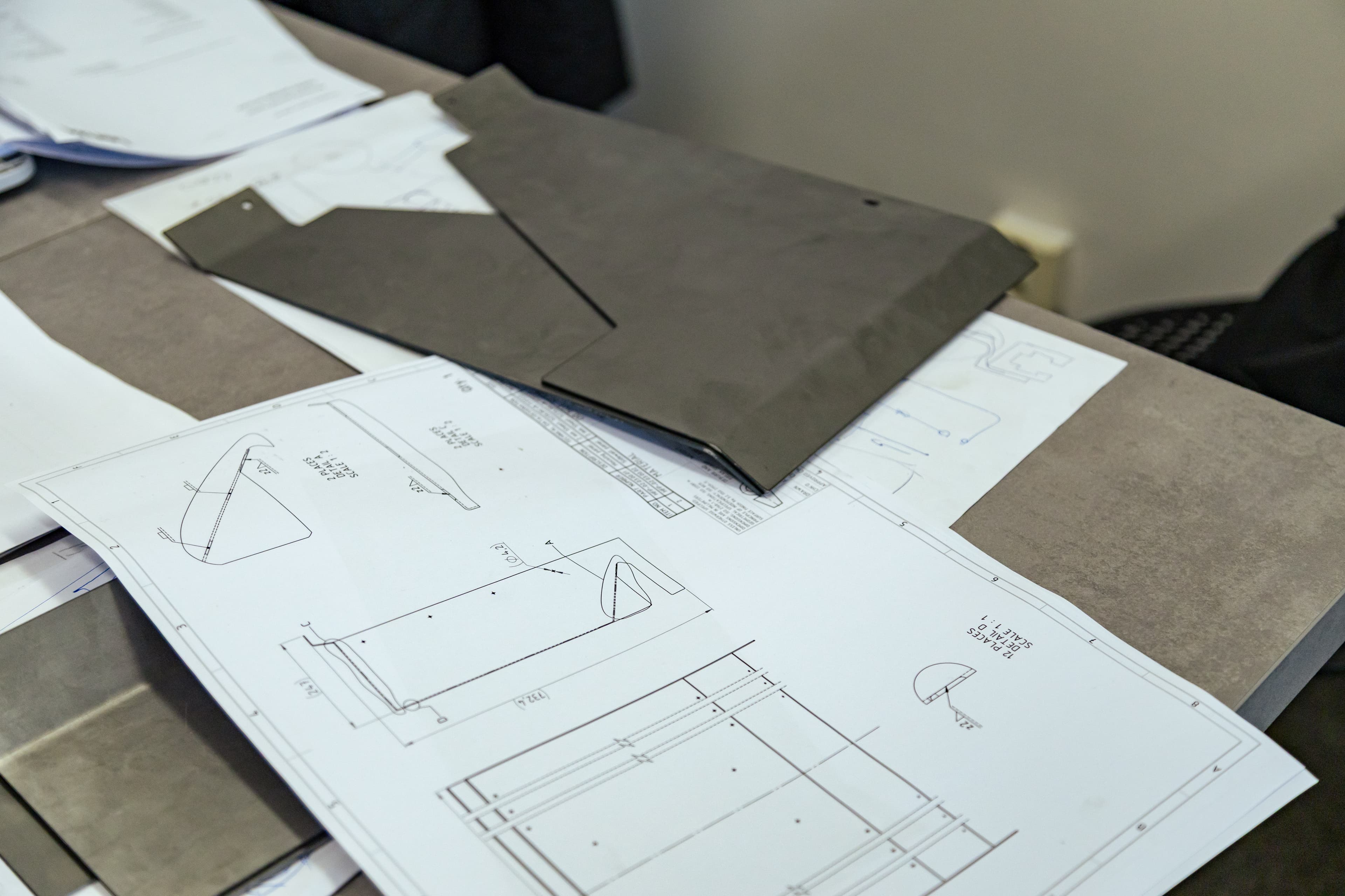
A DXF on its own carries only the cut geometry — it says nothing about threads, countersinks, bend direction, or which dimension is critical. For a simple flat part a clean DXF is enough. But as soon as the part has machined features, bends, or precise fits, attach a simple 2D drawing (PDF) or a 3D model as well. The extra documentation removes guesswork and speeds up quoting.
- The part is bent — direction and angle must be specified
- Holes need to be tapped or countersunk
- Some dimensions are critical and need a tolerance
- Press-fit hardware (nuts, standoffs) is inserted
Dimensions and tolerances
Draw the part at 1:1 scale and dimension it in millimetres. Do not slap a tight tolerance on every dimension — it raises the price for no reason. Call out only the dimensions that are genuinely critical for assembly or fit, and give each one a concrete tolerance. Dimension critical features from a single reference edge, not in a chain, so the tolerances do not stack up. A typical achievable laser-cutting tolerance is around ±0.1 mm on thinner sheets.
Threads, countersinks and holes
A bare hole in a DXF does not say whether it should be a through hole, tapped, or countersunk. Describe these features in the accompanying drawing: for a thread give the type and size (e.g. M5), for a countersink give the angle and major diameter (e.g. 90° for a flat-head screw). For press-fit hardware specify the exact type and the side it is inserted from.
- Keep the smallest hole at least equal to the material thickness
- For a thread, state the size and standard (e.g. M5, M6)
- For a countersink, state the angle and head diameter
- Leave at least 2× thickness between holes and from edges
Bends and thickness
Mark a bend in a 2D file with a line at the centre of the bend on a separate layer (ideally a dashed line). State the bend direction (up/down) and the angle. The inside radius is usually set by the material thickness — do not specify your own unrealistic radii. Keep holes and cutouts a safe distance from the bend line, otherwise they deform during bending. For more complex bent parts, supplying a 3D model directly is the safest option.
Units, scale and format
Always export the file at 1:1 scale and in millimetres — no scaling or conversions. For 2D geometry use vector formats: DXF (version R12 or R14) or DWG. For parts with bends or machining, a 3D model in STEP format is the most reliable. After exporting, always verify the overall part size against the intended values — a tiny unit error can turn hundreds of millimetres into centimetres.
Ten DXF mistakes that break an automatic quote
Every example below comes from files we actually receive. Each one changes what the configurator measures — and therefore the price you are shown.
1. Open contour
In the configurator: The design review flags Open contour. If the outer outline is open, the part has no usable surface area and no price is calculated at all.
Fix: Join the segments into a single closed polyline (JOIN / PEDIT). A 0.01 mm gap already counts as open.
2. Doubled lines
In the configurator: A Duplicate path warning. The same edge is measured twice, so the cut length — and the price with it — rises for nothing.
Fix: Run OVERKILL (delete duplicate objects) before exporting, and check that no contour has been copied exactly onto itself.
3. Hole smaller than the sheet thickness
In the configurator: A Hole too small warning. In production such a hole burns rather than cuts cleanly.
Fix: Keep every hole at least as wide as the material is thick — 3 mm sheet, 3 mm hole. Anything smaller has to be drilled.
4. Live text instead of outlines
In the configurator: TEXT and MTEXT add nothing to the cut length, but they do enlarge the measured size of the part.
Fix: Convert lettering to closed outlines, or move it to a separate engraving layer and select engraving in the configurator.
5. Frame, title block and dimensions left in the file
In the configurator: The overall size is measured across the frame, so a 200 mm part reads as 420 mm — the wrong blank, the wrong price, sometimes Price on request.
Fix: Export cut geometry only. Dimensions belong in a separate PDF drawing attached to the order.
6. Geometry left inside a block
In the configurator: The contents of a block reference (INSERT) are not counted into the cut length — the preview looks right while the measured cut length stays at zero.
Fix: Explode blocks down to plain lines, arcs and polylines before exporting.
7. Construction geometry hidden instead of deleted
In the configurator: Entities on a switched-off or frozen layer are not drawn in the preview, yet they still count towards the part size and the cut length. The preview looks perfect and the price is wrong.
Fix: Delete the contents of auxiliary layers — switching the layer off is not enough.
8. Hatch fills
In the configurator: A hatch boundary is read as a cut path: phantom cut length now, and a laser that would try to cut the fill later.
Fix: Delete every hatch. Describe the surface finish in the accompanying drawing instead.
9. Inches or a scaled drawing
In the configurator: Numbers in the file are read as millimetres whatever the drawing units say. A 4 × 2 inch part arrives as 4 × 2 mm — full of Hole too small warnings and priced at a fraction of the real part.
Fix: Export 1:1 in millimetres, then compare the size shown after upload with the size you intended.
10. Part drawn in a layout (paper space)
In the configurator: Only model space is read. An empty model space means no preview, no geometry and no price.
Fix: Move the geometry into model space and export it from there.
What the configurator expects from the file
These are the hard requirements. A file that meets all of them is priced within seconds of being uploaded.
| Requirement | Value | If it does not match |
|---|---|---|
| File format | .dxf (ASCII) | A binary DXF, a DWG, a PDF, a STEP or a renamed file is skipped during upload. |
| DXF version | R12 – R2018 | A structurally damaged file cannot be opened and no preview is generated. |
| File size | max 8 MB per file | The file is skipped with the 8 MB limit message. |
| Units and scale | mm, 1:1 | Values are read as millimetres; a drawing in inches comes out 25.4× too small. |
| Where the geometry lives | model space | An empty model space means no entities, no preview and no price. |
| Contours | closed, no gaps or overlaps | Without a usable surface area the quote fails. |
| File content | cut geometry only | Dimensions, frames, hatches and text distort both the size and the cut length. |
| Layers | cut / engrave / bend separated | Everything left in the file is measured — including entities on hidden layers. |
| Blocks | exploded | The contents of a block add no cut length. |
| Parts per file | 1 part, quantity set in the configurator | The per-file base fee is charged again for every extra file. |
| Number of files | guest 1, signed in unlimited | A second file asks you to create an account before it is processed. |
How the price is calculated from your DXF
Half of the inputs come out of the file itself, the other half you choose in the configurator. Anything the file gets wrong is carried straight into the price.
Read from the file
- Overall size (bounding box) — decides the blank and whether the part fits a sheet at all
- Enclosed area — the basis for material consumption and weight
- Total cut length — every contour, every hole, every forgotten line
- Number of entities and layers — program preparation and machine setup
- Number of closed inner contours — one pierce per hole
Chosen in the configurator
- Material and thickness — together with the area this gives the weight and the material cost
- Quantity — setup is spread across the batch, so the unit price falls as quantity rises
- Additional services — engraving, deburring, coating
A base fee is charged once per uploaded file, not per piece. Ten identical parts belong in one file with quantity 10 — uploading the same DXF ten times pays that fee ten times. If a part falls outside the automatic envelope (larger than the sheet, or no machine fits it), the item is marked Price on request and cannot be checked out online until we confirm it.
Configurator messages and what they mean
Six messages cover almost every file that fails to price. The cause is nearly always in the list above.
| Message | Cause | What to do |
|---|---|---|
| 1 file was skipped. Only DXF files are supported. | The file is not a .dxf — usually a DWG, a PDF, a STEP or an image. | Export or save as DXF (ASCII) and upload it again. |
| 1 file was skipped for exceeding the 8 MB limit. | Usually thousands of tiny segments, hatches, or an imported raster image. | Delete hatches and text, simplify curves and re-export as R12. |
| Preview not available | The file could not be read or rendered: a binary DXF, a damaged structure, or nothing in model space. | Re-export as ASCII DXF R12/R14 with the part in model space. |
| … has no usable surface area, so it can’t be priced automatically. | Open contours — the outline is a set of loose lines rather than a closed shape. | Close the outer contour, then upload the file again. |
| We couldn’t price … automatically. | The geometry contains elements the pricing engine cannot read. | Work through the checklist below, or request a manual quote — we will price it by hand. |
| Price on request | The part is outside the automatic pricing envelope — typically larger than the sheet we can cut. | Split the part, or contact us: the item cannot be checked out online until we confirm it. |
Pre-flight checklist before uploading
Thirteen checks, two minutes of work, and the configurator prices the file on the first attempt.
- Exported as DXF (ASCII), version R12 or R14.
- Millimetres, scale 1:1, overall size checked against the drawing.
- Geometry in model space, one part per file.
- Every cut contour closed, with no gaps.
- No duplicate or overlapping lines.
- Blocks exploded into plain geometry.
- Text converted to outlines, or on its own engraving layer.
- Dimensions, frame, title block, centre lines and hatches deleted.
- Auxiliary layers deleted, not merely switched off.
- Holes at least as wide as the material is thick.
- At least 2× the thickness between holes and from holes to edges.
- After uploading, the size in the preview compared with the intended size.
- Design review panel worked through — every warning either fixed or consciously accepted.
Correct DXF files to download
Four real production files that pass our configurator without a single warning, ordered from the simplest possible part to a complex profile. Download them and open them in your own CAD: you will see exactly what clean cutting geometry looks like, and you can use them as a template for your own export.
Plate with rounded corners
The simplest correct file there is: one closed outer contour made of four lines and four R5.5 arcs. No holes, no dimensions, no drawing frame — just the shape to be cut.
- Size
- 75 × 35 mm
- Contours
- 1
- Version
- AC1015 (R2000)
Plate with a hole
The same plate plus one Ø16.5 mm hole. The hole is not tagged in any way and does not sit on its own layer — it is simply another closed contour inside the outline. The configurator works out what is part and what is cut-out from the nesting.
- Size
- 75 × 35 mm
- Contours
- 2
- Version
- AC1015 (R2000)
Bracket with two holes
The outer contour mixes straight lines with R20 and R4 arcs, and holds Ø30 and Ø12.5 mm bores. Both are larger than typical sheet thickness, so the laser cuts them cleanly — the “hole ≥ material thickness” rule in practice.
- Size
- 80 × 100 mm
- Contours
- 3
- Version
- AC1015 (R2000)
Saw blade — a complex profile
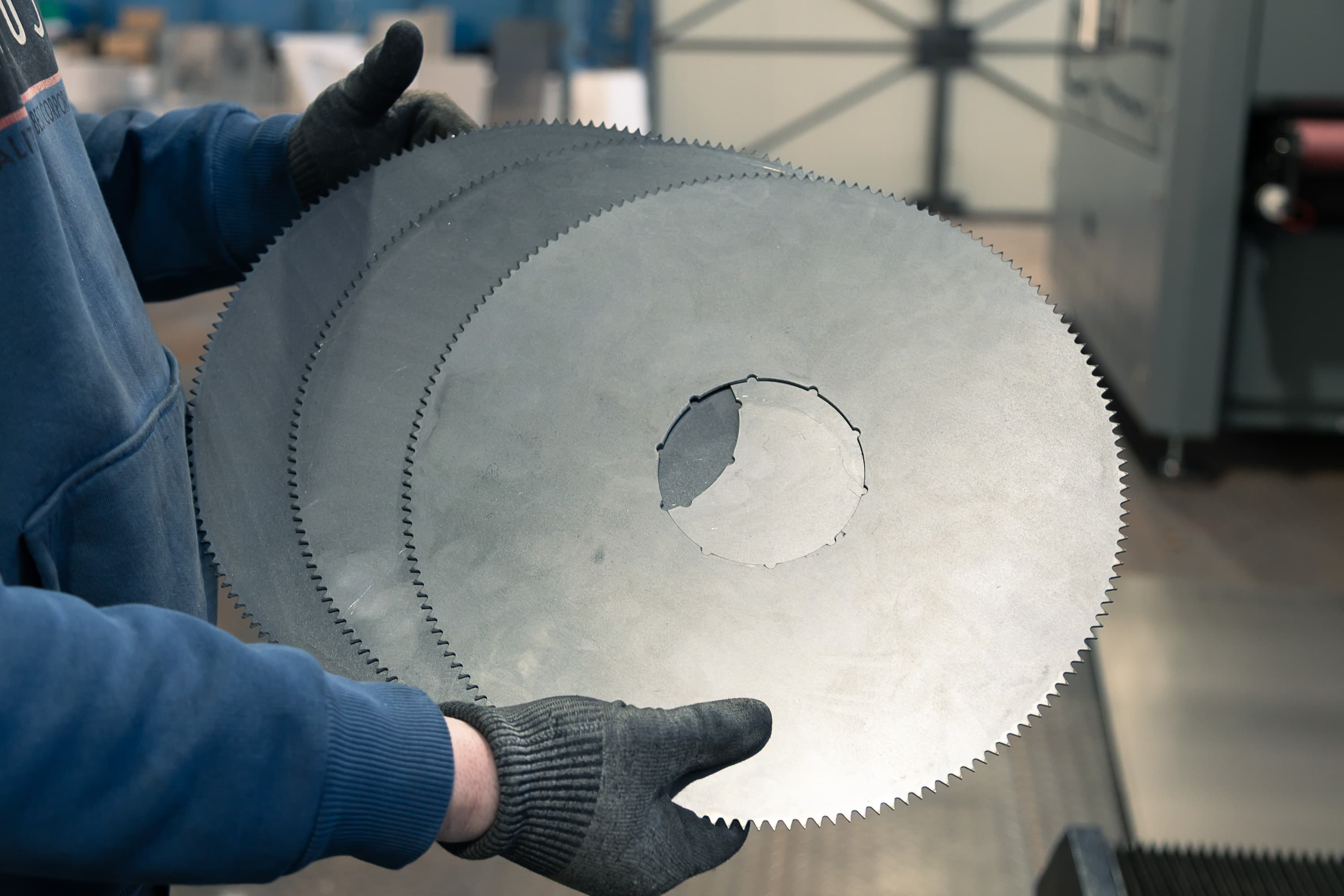
A 180 mm blade with 60 teeth is one closed curve of 240 vertices, not hundreds of separate segments. Even geometry this involved stays a single polyline; the centre carries a hexagonal 25.4 mm across-corners bore.
- Size
- 179.9 × 179.9 mm
- Contours
- 2
- Version
- AC1014 (R14)
What all four have in common
- Geometry lives in model space, not paper space
- Everything on one layer, line width 0.00 mm
- Units in millimetres ($INSUNITS = 4)
- Every contour is closed — zero loose ends
- No text, dimensions, frames or blocks
The files are saved as R14 and R2000; the configurator reads both. If your CAD offers a newer version, prefer R12 or R14 — the older formats carry nothing that could be interpreted ambiguously.
Conclusion
A properly prepared DXF file saves time and money — it reduces the risk of errors, speeds up quoting, and ensures you get exactly what you designed. If in doubt, contact us before placing your order.